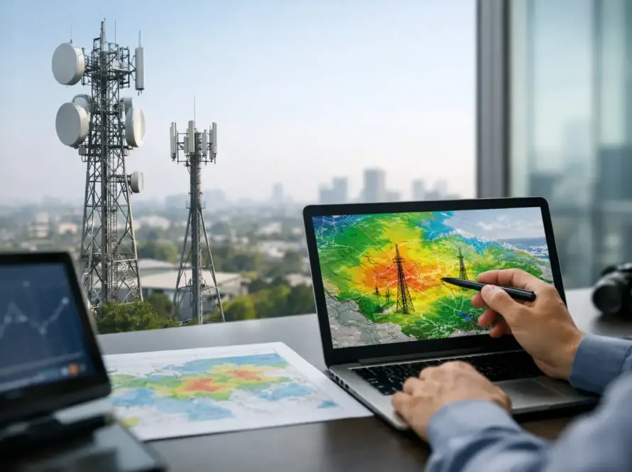
A radio system can have quality equipment, properly programmed channels, and trained users yet still fail at the moment it is needed if the antenna is installed in the wrong place. Antenna placement for coverage is where system design becomes real-world performance. For organizations operating across the U.S. Virgin Islands, that means accounting for steep terrain, concrete construction, salt exposure, vegetation, changing weather, and the distance between islands.
The goal is not simply to mount an antenna as high as possible. The goal is to create dependable signal paths where people work, travel, respond, and operate. That requires a site-specific plan built around the service area, the radio technology, and the consequences of a missed call.
Antenna Placement for Coverage Starts With the Service Area
Before selecting a rooftop, tower, or mast, define where coverage is actually required. A marina may need reliable communications from dock offices to vessels near the harbor entrance. A resort may need coverage in guest areas, maintenance spaces, parking facilities, and service corridors. A public-sector operation may need dependable communication between offices, vehicles, remote facilities, and personnel working outside.
This distinction matters because a coverage map is not the same as an operational map. A signal that is usable outdoors may be inadequate inside a concrete equipment room. A location that serves one side of a hillside may leave the opposite slope in shadow. Coverage planning should identify priority areas, secondary areas, known dead zones, and places where a backup method is necessary.
For multi-island organizations, a single centrally located antenna may not be the best answer. Radio signals generally travel in straight paths and do not naturally follow roads, bend around ridges, or pass easily through dense structures. Saint Thomas, Saint John, and Saint Croix each present different terrain and infrastructure conditions. In some cases, distributed sites, repeaters, or networked radio solutions provide a more dependable result than trying to force one antenna location to serve every operating area.
Height Helps, but Line of Sight Decides
Elevation is valuable because it improves line of sight and reduces the number of obstructions between the transmitting antenna and the user. A rooftop installation can outperform a ground-level installation by a wide margin. However, height alone does not guarantee better coverage.
An antenna placed high on the wrong side of a hill, behind a taller structure, or beneath nearby metalwork can still produce uneven results. On island terrain, a ridge can block a signal completely while a location only a short distance away may have a clear path to the intended coverage area. This is why site walks, terrain review, and field testing should guide the final decision.
There is also a practical ceiling to antenna height. Taller structures may require more complex mounting, lightning protection, grounding, wind-load engineering, permitting, and maintenance access. For a business system, the best location is often the one that provides the needed performance with reasonable installation and lifecycle requirements, not the highest point visible on the property.
Watch for Near-Field Obstructions
Objects close to an antenna can affect its pattern and efficiency. Metal roofs, HVAC units, solar arrays, railings, water tanks, other antennas, and structural steel can reflect or absorb radio energy. An antenna mounted beside a large metal object may send more signal in one direction and less in another, creating coverage gaps that are difficult to predict from a desk.
Give the antenna appropriate separation from nearby structures whenever possible. The required distance depends on the antenna type, frequency band, mounting configuration, and surrounding environment. A qualified installer can evaluate these factors rather than relying on a universal rule of thumb.
Match the Antenna Pattern to the Job
Antenna selection and placement work together. An omnidirectional antenna is designed to radiate broadly around its location and can be suitable when users operate in many directions from a central site. A directional antenna concentrates energy toward a defined area and can be more effective for a remote facility, a coastal route, an inter-island path, or a location where coverage is needed primarily in one direction.
Neither option is automatically better. An omnidirectional antenna may leave weak areas at the edge of a large, irregular service area. A directional antenna may provide stronger performance where it points but create limited coverage behind it. Sector antennas and multiple-site designs can address complex properties, but they also introduce more equipment, coordination, and maintenance considerations.
The same principle applies indoors. A powerful exterior antenna may not reliably serve lower floors, interior rooms, basements, or reinforced concrete areas. In-building distributed antenna systems, strategically placed indoor antennas, or additional radio infrastructure may be required when indoor communications are operationally critical.
Account for Cable Loss and Equipment Location
The antenna can be in an excellent location while the system still underperforms because of excessive coaxial cable loss. Radio-frequency energy decreases as it travels through cable, and longer cable runs generally mean more loss. Higher frequencies and lower-quality cable can make this issue more pronounced.
This creates a common trade-off. A remote high point may offer clear line of sight, but reaching it with a long cable run can reduce the benefit. In some designs, locating active equipment closer to the antenna or using appropriately specified low-loss cable produces better overall performance. The right approach depends on the system architecture, power availability, environmental protection, and maintenance access.
Connectors, lightning arrestors, grounding hardware, and weatherproofing also affect reliability. A poor connector installation can introduce signal loss or intermittent faults. In a marine or coastal environment, salt air and moisture accelerate corrosion. Every exterior connection should be properly sealed, strain-relieved, and inspected as part of a preventive maintenance plan.
Design for Weather, Salt, and Access
Antenna placement is not complete when the initial coverage test passes. The site must remain serviceable through wind, rain, sun exposure, and coastal conditions. Mounting hardware should be rated for the environment and secured to an appropriate structure. Unsupported masts, improvised brackets, and unprotected cabling can turn a functioning installation into an avoidable outage.
Lightning protection and grounding deserve particular attention. A properly designed protection system helps reduce risk to radios, network equipment, and connected facilities. It is not a substitute for sound installation practices, but it is a core part of resilient communications infrastructure.
Access is equally important. If technicians cannot safely reach the antenna, cable path, or grounding components, routine inspection becomes difficult and repairs take longer. A slightly less elevated but accessible installation may be the more dependable choice over time. Operations leaders should consider maintenance from the beginning, not after a fault develops.
Verify Coverage With Field Testing
Desktop planning is valuable, but radio coverage should be tested where users actually work. Conduct tests at realistic times and under realistic conditions. A clear signal at an empty facility may behave differently when vehicles, machinery, vessels, weather, and personnel are present.
Testing should evaluate more than whether a radio receives audio. Assess voice clarity, transmit reliability, signal strength, call setup behavior, and performance at the edges of the intended service area. For digital systems, a signal may appear present while audio quality or data performance is inconsistent. Document results so the team can distinguish an isolated weak spot from a system-wide design issue.
It is also wise to test with the radio models, accessories, and carrying positions users will have in the field. A radio worn at the waist, used inside a vehicle, or operated in a noisy equipment area does not perform exactly like a handheld unit held in open space. Coverage design should reflect user conditions, not ideal conditions.
Know When a Single Antenna Is Not Enough
Some coverage problems cannot be solved by relocating one antenna. Large facilities, separated worksites, steep terrain, and high-reliability requirements may call for repeaters, linked sites, fixed wireless infrastructure, or push-to-talk over cellular as part of a broader communications plan.
This is where technology choices should follow the operational requirement. Conventional analog systems can be effective for straightforward local communications. Digital mobile radio can add capacity, features, and management capability. Push-to-talk over cellular may extend communications beyond local radio range where cellular or satellite-supported connectivity is available. The strongest solution is often a coordinated design that uses each technology where it makes sense.
Cwave Communications, an authorized Hytera Dealer, approaches placement as part of the full communications system: site conditions, equipment selection, installation quality, coverage validation, and long-term support. That approach helps organizations avoid spending on hardware that cannot overcome a preventable site-design problem.
Antenna placement should be treated as an operational decision, not a finishing detail. Start with where communications must work, test the assumptions in the field, and build in the protection and access needed to keep the system performing long after installation day.